Showing posts with label Construction Equipment. Show all posts

Monday, November 8, 2010

Earthmoving Data

SOIL CLASSIFICATION FOR EARTH-MOVING OPERATIONS
Various classifications have been established properly for soil depending on the purposes of earth-moving operations. Generally speaking, however, detailed classifications of soil are not required for the ordinary earth-moving operations.

Rather, attention is required to be given to whether the soil to be handled is of special ores or contains special
clay minerals. Hereinafter is described the knowledge necessary for earth work planning prior to such operations as digging, loading, hauling, pushing (spreading), rolling compaction, etc., on ordinary terrain.

* Data (figures) to be given hereinafter vary largely depending on various operating and environmental conditions. Consequently, before starting the earth work, tests should be conducted to obtain correct data for operations.

Some knowledge of the weight data per unit volume of materials of their major ingredients is important for their handling or hauling in mines, etc.. The specific weight data of some major types of soil and ingredients are given below.

WEIGHT DATA OF MATERIALS


Hauling Performance of Construction Machines
HAULING PERFORMANCE OF CONSTRUCTION MACHINES
INTRODUCTION
"What Model or type of a tractor is most suitable to pull this trailer?" "Is this bulldozer capable of going up this hill while pulling that scraper loaded full?" In order to give explicit answers to these questions, it is necessary to have the right understanding of the hauling performance of vehicles.


For easy understanding, let us explain the hauling performance with the following machine capabilities and
related elements.
(1) The inherent machine capability
(2) Elements limiting the inherent machine capability
(3) Machine capabilities required for earthmoving operations

INHERENT MACHINE CAPABILITY
1. What is the inherent machine capability?
a) Output power
The engine horsepower of a construction machine is the most essential power of those developed by the machine itself. This can be estimated by multiplying one element (traction force) by another element (a travel speed). Accordingly, where the engine of a machine develops a rated power; the smaller the travel speed, the larger the traction force or drawbar pull will be. On the contrary, the larger the travel speed, the smaller the drawbar pull.

b) Gear-shifting
Gear-shifting is effected to determine the optimum drawbar pull and travel speed required for accomplishing a given job. Therefore, a machine has several gears to be selected by shifting for the optimum travel speed.

2. Direct-drive type tractor
The table below gives the drawbar pull and travel speeds of a direct-drive type bulldozer.


The rated drawbar pull is such a traction force that can be developed at the rated engine power and the rated revolutions (rpm). The rated drawbar pull is normally estimated by taking into account the travelling resistance (which will be explained later) and the mechanical loss of power in its line from the engine to the sprockets.

The maximum drawbar pull is the maximum traction force that can be developed by a machine and is estimated from the maximum engine torque. In other words, the maximum drawbar pull of a machine can be developed by the lugging ability of its prime mover and is practically obtained in a low gear. Consequently, the maximum drawbar pull is shown only at F1 on the specifications.

3. TORQFLOW-drive type tractor
In a TORQFLOW-drive type tractor, the relationships between the travel speeds and drawbar pull are obtained from the combined performance between the engine and the torque converter. In a TORQFLOW-drive machine, it is difficult to relate both the drawbar pull and travel speeds directly to the engine revolutions. Thus, the hauling performance is indicated by curves. The graph at right gives the hauling performance curves of the TORQFLOW-drive type bulldozer.

ELEMENTS LIMITING THE INHERENT MACHINE CAPABILITY
1. What are the elements limiting the inherent machine capability or power? These are;
a) Traction between the undercarriage (tracks or wheels) and the road surface.
b) Altitude
Altitude in b) will be described in a separate issue and herein is examined the problem of traction between the undercarriage and the road surface.

2. Traction between the undercarriage and road surface
"When a motor vehicle cannot be moved due to slipping on the snow-covered road, what should be done to move the vehicle?"
The answers are;
Solution
(1) Add load to the driving wheels.
(2) Install chain to the wheel tires or replace the tires with the spiked type.
(3) Scatter sand or spread straw mats on the road surface.
Reason
(1) The traction force is increased with the added load.
(2) The undercarriage is made so as to develop more traction.
(3) The critical traction force is increased by the higher coefficient of traction.

The above facts can also be applied to a crawler tractor. Now, let us look at the coefficient of cohesion and the critical traction force or traction used in the above table. The critical traction is the maximum traction available depending on the cohesive condition of the road surface. This can be estimated by the following formula.

MACHINE CAPABILITIES REQUIRED FOR EARTHMOVING OPERATIONS.
1. What are the elements limiting the machine capabilities required for earthmoving operations?
When a truck is traveling on the road or going uphill, the following phenomena will be encountered as a matter of course.

Phenomenon
(1) The travel speed of a truck with load on the flat road should vary when the same truck with the same load travels on the rugged or rutted surface.
(2) When traveling on the flat road or going uphill in the same operating gear, the travel speed should vary as a matter of course.
Influential element
(1) Rolling resistance
(2) Grade resistance

2. Rolling resistance
When a vehicle is traveling on the ground or road, the retarding force of ground against wheels or tracks should take place. Such a resistance varies depending on the ground or road surface conditions. The rolling resistance is measured in the ratio to the vehicle weight and can be estimated by the following formula.
Wr = μr•G
Where, 
Wr: Rolling resistance (kg) 
μr: Coefficients of rolling resistance
G: Vehicle operating weight

The coefficient of rolling resistance can be selected from among those given in the table below, according to the ground or road surface conditions. The coefficient of rolling resistance can be selected from among those given in the table below, according to the ground or road surface conditions.
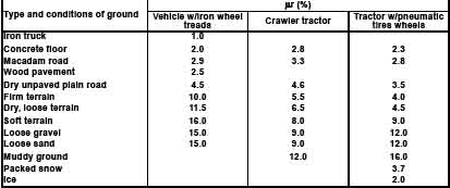

In a crawler tractor, too, the rolling resistance should vary depending on the type of applied soil. The representative values of rolling resistance, however, are taken into account in preparing the curves for drawbar pull and hauling performance of crawler tractors. Therefore, the varying rolling resistance may practically be ignored.

Conditions
- Uphill traveling
- Traveling on flat, level surface
- Downhill traveling
Haul resistance
- Rolling resistance + grade resistance
- Rolling resistance.
- Rolling resistance – grade resistance

Example (6) What is the hauling resistance against the D60-6 tractor going uphill at 4° in a dry, loose terrain, while pulling an RS08 scraper with maximum load?

Solution: 
The gross weight of the RS08 with maximum load is 18870 kg.
The rolling resistance factor is 0.045. 
Thus, the rolling resistance is 0.045 × 18870 = 850 kg
The weight of the D60-6 tractor is 12550 kg.
The gross weight of the RS08 is 18870 kg.
Then, the total weight of both machines is 31420 kg
Consequently, the grade resistance is 0.07 × 31420 = 2200 kg.
Thus, the hauling resistance is 850 + 2200 = 3050 kg.

SUMMARY AND APPLICATION
1. Summary


2. Application
Example (7) Assume that the D65 tractor is used to pull a wheeled wagon (the empty weight: 17 tons) with a 50-ton load in a dry, loose terrain. What are the operating gears and the corresponding approx. travel speeds available on a flat, level ground? What is the degree of a hill climbable under the same condition?

Solution: 
The rolling resistance
Weight of the wagon (empty): 17000 kg 
Payload: 50000 kg
Total weight: 67000 kg 
Coefficient of rolling resistance: 0.045
Consequently the rolling resistance against the wagon is 67000 × 0.045 = 3015 kg

TRAFFICABILITY
Operating efficiency of a construction machine depends largely on the ground surface on which the machine travels. In clay, loam or clayey soil high in water or moisture content, the bearing force of soil is low and a ''kneading'' phenomenon is liable to occur. Consequently, there are cases where a construction machine cannot be operated because of the type and conditions of soil. The degree of the traveling capability of a construction machine is called the traffic-ability.

In general, traffic-ability is indicated by a cone index No. (The method of measuring a cone index No. will be
described later.). The larger the cone index number becomes, the higher the traffic-ability of the machine will become. In other words, on the soil larger in cone index No., a construction machine will be able to travel easier. The minimum cone index numbers required for various types of construction machines to perform digging, hauling operations, etc. are given below.


NOTE:
In determining a cone index, apply the cone penetrometer at 3 or 4 points at least to average the variations in the measured values.

* Cone index numbers (qc)
A cone index number is measured by means of a cone penetro-meter in a cone penetration test.
A rod with a cone at the tip is pushed into the soil by hand.
The pressure required to advance the cone at a slow constant rate is known as the penetration resistance.
The penetration resistance is read out on the dial gauge.
Thereby, the shearing strength of soil can be estimated.
Then, a cone index number can be obtained by referring the estimated shearing strength to the conversion table attached to the meter.

Earthmoving Data

SOIL CLASSIFICATION FOR EARTH-MOVING OPERATIONS
Various classifications have been established properly for soil depending on the purposes of earth-moving operations. Generally speaking, however, detailed classifications of soil are not required for the ordinary earth-moving operations.

Rather, attention is required to be given to whether the soil to be handled is of special ores or contains special
clay minerals. Hereinafter is described the knowledge necessary for earth work planning prior to such operations as digging, loading, hauling, pushing (spreading), rolling compaction, etc., on ordinary terrain.

* Data (figures) to be given hereinafter vary largely depending on various operating and environmental conditions. Consequently, before starting the earth work, tests should be conducted to obtain correct data for operations.

Some knowledge of the weight data per unit volume of materials of their major ingredients is important for their handling or hauling in mines, etc.. The specific weight data of some major types of soil and ingredients are given below.

WEIGHT DATA OF MATERIALS


Hauling Performance of Construction Machines
HAULING PERFORMANCE OF CONSTRUCTION MACHINES
INTRODUCTION
"What Model or type of a tractor is most suitable to pull this trailer?" "Is this bulldozer capable of going up this hill while pulling that scraper loaded full?" In order to give explicit answers to these questions, it is necessary to have the right understanding of the hauling performance of vehicles.


For easy understanding, let us explain the hauling performance with the following machine capabilities and
related elements.
(1) The inherent machine capability
(2) Elements limiting the inherent machine capability
(3) Machine capabilities required for earthmoving operations

INHERENT MACHINE CAPABILITY
1. What is the inherent machine capability?
a) Output power
The engine horsepower of a construction machine is the most essential power of those developed by the machine itself. This can be estimated by multiplying one element (traction force) by another element (a travel speed). Accordingly, where the engine of a machine develops a rated power; the smaller the travel speed, the larger the traction force or drawbar pull will be. On the contrary, the larger the travel speed, the smaller the drawbar pull.

b) Gear-shifting
Gear-shifting is effected to determine the optimum drawbar pull and travel speed required for accomplishing a given job. Therefore, a machine has several gears to be selected by shifting for the optimum travel speed.

2. Direct-drive type tractor
The table below gives the drawbar pull and travel speeds of a direct-drive type bulldozer.


The rated drawbar pull is such a traction force that can be developed at the rated engine power and the rated revolutions (rpm). The rated drawbar pull is normally estimated by taking into account the travelling resistance (which will be explained later) and the mechanical loss of power in its line from the engine to the sprockets.

The maximum drawbar pull is the maximum traction force that can be developed by a machine and is estimated from the maximum engine torque. In other words, the maximum drawbar pull of a machine can be developed by the lugging ability of its prime mover and is practically obtained in a low gear. Consequently, the maximum drawbar pull is shown only at F1 on the specifications.

3. TORQFLOW-drive type tractor
In a TORQFLOW-drive type tractor, the relationships between the travel speeds and drawbar pull are obtained from the combined performance between the engine and the torque converter. In a TORQFLOW-drive machine, it is difficult to relate both the drawbar pull and travel speeds directly to the engine revolutions. Thus, the hauling performance is indicated by curves. The graph at right gives the hauling performance curves of the TORQFLOW-drive type bulldozer.

ELEMENTS LIMITING THE INHERENT MACHINE CAPABILITY
1. What are the elements limiting the inherent machine capability or power? These are;
a) Traction between the undercarriage (tracks or wheels) and the road surface.
b) Altitude
Altitude in b) will be described in a separate issue and herein is examined the problem of traction between the undercarriage and the road surface.

2. Traction between the undercarriage and road surface
"When a motor vehicle cannot be moved due to slipping on the snow-covered road, what should be done to move the vehicle?"
The answers are;
Solution
(1) Add load to the driving wheels.
(2) Install chain to the wheel tires or replace the tires with the spiked type.
(3) Scatter sand or spread straw mats on the road surface.
Reason
(1) The traction force is increased with the added load.
(2) The undercarriage is made so as to develop more traction.
(3) The critical traction force is increased by the higher coefficient of traction.

The above facts can also be applied to a crawler tractor. Now, let us look at the coefficient of cohesion and the critical traction force or traction used in the above table. The critical traction is the maximum traction available depending on the cohesive condition of the road surface. This can be estimated by the following formula.

MACHINE CAPABILITIES REQUIRED FOR EARTHMOVING OPERATIONS.
1. What are the elements limiting the machine capabilities required for earthmoving operations?
When a truck is traveling on the road or going uphill, the following phenomena will be encountered as a matter of course.

Phenomenon
(1) The travel speed of a truck with load on the flat road should vary when the same truck with the same load travels on the rugged or rutted surface.
(2) When traveling on the flat road or going uphill in the same operating gear, the travel speed should vary as a matter of course.
Influential element
(1) Rolling resistance
(2) Grade resistance

2. Rolling resistance
When a vehicle is traveling on the ground or road, the retarding force of ground against wheels or tracks should take place. Such a resistance varies depending on the ground or road surface conditions. The rolling resistance is measured in the ratio to the vehicle weight and can be estimated by the following formula.
Wr = μr•G
Where, 
Wr: Rolling resistance (kg) 
μr: Coefficients of rolling resistance
G: Vehicle operating weight

The coefficient of rolling resistance can be selected from among those given in the table below, according to the ground or road surface conditions. The coefficient of rolling resistance can be selected from among those given in the table below, according to the ground or road surface conditions.


In a crawler tractor, too, the rolling resistance should vary depending on the type of applied soil. The representative values of rolling resistance, however, are taken into account in preparing the curves for drawbar pull and hauling performance of crawler tractors. Therefore, the varying rolling resistance may practically be ignored.

Conditions
- Uphill traveling
- Traveling on flat, level surface
- Downhill traveling
Haul resistance
- Rolling resistance + grade resistance
- Rolling resistance.
- Rolling resistance – grade resistance

Example (6) What is the hauling resistance against the D60-6 tractor going uphill at 4° in a dry, loose terrain, while pulling an RS08 scraper with maximum load?

Solution: 
The gross weight of the RS08 with maximum load is 18870 kg.
The rolling resistance factor is 0.045. 
Thus, the rolling resistance is 0.045 × 18870 = 850 kg
The weight of the D60-6 tractor is 12550 kg.
The gross weight of the RS08 is 18870 kg.
Then, the total weight of both machines is 31420 kg
Consequently, the grade resistance is 0.07 × 31420 = 2200 kg.
Thus, the hauling resistance is 850 + 2200 = 3050 kg.

SUMMARY AND APPLICATION
1. Summary


2. Application
Example (7) Assume that the D65 tractor is used to pull a wheeled wagon (the empty weight: 17 tons) with a 50-ton load in a dry, loose terrain. What are the operating gears and the corresponding approx. travel speeds available on a flat, level ground? What is the degree of a hill climbable under the same condition?

Solution: 
The rolling resistance
Weight of the wagon (empty): 17000 kg 
Payload: 50000 kg
Total weight: 67000 kg 
Coefficient of rolling resistance: 0.045
Consequently the rolling resistance against the wagon is 67000 × 0.045 = 3015 kg

TRAFFICABILITY
Operating efficiency of a construction machine depends largely on the ground surface on which the machine travels. In clay, loam or clayey soil high in water or moisture content, the bearing force of soil is low and a ''kneading'' phenomenon is liable to occur. Consequently, there are cases where a construction machine cannot be operated because of the type and conditions of soil. The degree of the traveling capability of a construction machine is called the traffic-ability.

In general, traffic-ability is indicated by a cone index No. (The method of measuring a cone index No. will be
described later.). The larger the cone index number becomes, the higher the traffic-ability of the machine will become. In other words, on the soil larger in cone index No., a construction machine will be able to travel easier. The minimum cone index numbers required for various types of construction machines to perform digging, hauling operations, etc. are given below.


NOTE:
In determining a cone index, apply the cone penetrometer at 3 or 4 points at least to average the variations in the measured values.

* Cone index numbers (qc)
A cone index number is measured by means of a cone penetro-meter in a cone penetration test.
A rod with a cone at the tip is pushed into the soil by hand.
The pressure required to advance the cone at a slow constant rate is known as the penetration resistance.
The penetration resistance is read out on the dial gauge.
Thereby, the shearing strength of soil can be estimated.
Then, a cone index number can be obtained by referring the estimated shearing strength to the conversion table attached to the meter.

Earthmoving Data

SOIL CLASSIFICATION FOR EARTH-MOVING OPERATIONS
Various classifications have been established properly for soil depending on the purposes of earth-moving operations. Generally speaking, however, detailed classifications of soil are not required for the ordinary earth-moving operations.

Rather, attention is required to be given to whether the soil to be handled is of special ores or contains special
clay minerals. Hereinafter is described the knowledge necessary for earth work planning prior to such operations as digging, loading, hauling, pushing (spreading), rolling compaction, etc., on ordinary terrain.

* Data (figures) to be given hereinafter vary largely depending on various operating and environmental conditions. Consequently, before starting the earth work, tests should be conducted to obtain correct data for operations.

Some knowledge of the weight data per unit volume of materials of their major ingredients is important for their handling or hauling in mines, etc.. The specific weight data of some major types of soil and ingredients are given below.

WEIGHT DATA OF MATERIALS


Hauling Performance of Construction Machines
HAULING PERFORMANCE OF CONSTRUCTION MACHINES
INTRODUCTION
"What Model or type of a tractor is most suitable to pull this trailer?" "Is this bulldozer capable of going up this hill while pulling that scraper loaded full?" In order to give explicit answers to these questions, it is necessary to have the right understanding of the hauling performance of vehicles.


For easy understanding, let us explain the hauling performance with the following machine capabilities and
related elements.
(1) The inherent machine capability
(2) Elements limiting the inherent machine capability
(3) Machine capabilities required for earthmoving operations

INHERENT MACHINE CAPABILITY
1. What is the inherent machine capability?
a) Output power
The engine horsepower of a construction machine is the most essential power of those developed by the machine itself. This can be estimated by multiplying one element (traction force) by another element (a travel speed). Accordingly, where the engine of a machine develops a rated power; the smaller the travel speed, the larger the traction force or drawbar pull will be. On the contrary, the larger the travel speed, the smaller the drawbar pull.

b) Gear-shifting
Gear-shifting is effected to determine the optimum drawbar pull and travel speed required for accomplishing a given job. Therefore, a machine has several gears to be selected by shifting for the optimum travel speed.

2. Direct-drive type tractor
The table below gives the drawbar pull and travel speeds of a direct-drive type bulldozer.


The rated drawbar pull is such a traction force that can be developed at the rated engine power and the rated revolutions (rpm). The rated drawbar pull is normally estimated by taking into account the travelling resistance (which will be explained later) and the mechanical loss of power in its line from the engine to the sprockets.

The maximum drawbar pull is the maximum traction force that can be developed by a machine and is estimated from the maximum engine torque. In other words, the maximum drawbar pull of a machine can be developed by the lugging ability of its prime mover and is practically obtained in a low gear. Consequently, the maximum drawbar pull is shown only at F1 on the specifications.

3. TORQFLOW-drive type tractor
In a TORQFLOW-drive type tractor, the relationships between the travel speeds and drawbar pull are obtained from the combined performance between the engine and the torque converter. In a TORQFLOW-drive machine, it is difficult to relate both the drawbar pull and travel speeds directly to the engine revolutions. Thus, the hauling performance is indicated by curves. The graph at right gives the hauling performance curves of the TORQFLOW-drive type bulldozer.

ELEMENTS LIMITING THE INHERENT MACHINE CAPABILITY
1. What are the elements limiting the inherent machine capability or power? These are;
a) Traction between the undercarriage (tracks or wheels) and the road surface.
b) Altitude
Altitude in b) will be described in a separate issue and herein is examined the problem of traction between the undercarriage and the road surface.

2. Traction between the undercarriage and road surface
"When a motor vehicle cannot be moved due to slipping on the snow-covered road, what should be done to move the vehicle?"
The answers are;
Solution
(1) Add load to the driving wheels.
(2) Install chain to the wheel tires or replace the tires with the spiked type.
(3) Scatter sand or spread straw mats on the road surface.
Reason
(1) The traction force is increased with the added load.
(2) The undercarriage is made so as to develop more traction.
(3) The critical traction force is increased by the higher coefficient of traction.

The above facts can also be applied to a crawler tractor. Now, let us look at the coefficient of cohesion and the critical traction force or traction used in the above table. The critical traction is the maximum traction available depending on the cohesive condition of the road surface. This can be estimated by the following formula.

MACHINE CAPABILITIES REQUIRED FOR EARTHMOVING OPERATIONS.
1. What are the elements limiting the machine capabilities required for earthmoving operations?
When a truck is traveling on the road or going uphill, the following phenomena will be encountered as a matter of course.

Phenomenon
(1) The travel speed of a truck with load on the flat road should vary when the same truck with the same load travels on the rugged or rutted surface.
(2) When traveling on the flat road or going uphill in the same operating gear, the travel speed should vary as a matter of course.
Influential element
(1) Rolling resistance
(2) Grade resistance

2. Rolling resistance
When a vehicle is traveling on the ground or road, the retarding force of ground against wheels or tracks should take place. Such a resistance varies depending on the ground or road surface conditions. The rolling resistance is measured in the ratio to the vehicle weight and can be estimated by the following formula.
Wr = μr•G
Where, 
Wr: Rolling resistance (kg) 
μr: Coefficients of rolling resistance
G: Vehicle operating weight

The coefficient of rolling resistance can be selected from among those given in the table below, according to the ground or road surface conditions. The coefficient of rolling resistance can be selected from among those given in the table below, according to the ground or road surface conditions.


In a crawler tractor, too, the rolling resistance should vary depending on the type of applied soil. The representative values of rolling resistance, however, are taken into account in preparing the curves for drawbar pull and hauling performance of crawler tractors. Therefore, the varying rolling resistance may practically be ignored.

Conditions
- Uphill traveling
- Traveling on flat, level surface
- Downhill traveling
Haul resistance
- Rolling resistance + grade resistance
- Rolling resistance.
- Rolling resistance – grade resistance

Example (6) What is the hauling resistance against the D60-6 tractor going uphill at 4° in a dry, loose terrain, while pulling an RS08 scraper with maximum load?

Solution: 
The gross weight of the RS08 with maximum load is 18870 kg.
The rolling resistance factor is 0.045. 
Thus, the rolling resistance is 0.045 × 18870 = 850 kg
The weight of the D60-6 tractor is 12550 kg.
The gross weight of the RS08 is 18870 kg.
Then, the total weight of both machines is 31420 kg
Consequently, the grade resistance is 0.07 × 31420 = 2200 kg.
Thus, the hauling resistance is 850 + 2200 = 3050 kg.

SUMMARY AND APPLICATION
1. Summary


2. Application
Example (7) Assume that the D65 tractor is used to pull a wheeled wagon (the empty weight: 17 tons) with a 50-ton load in a dry, loose terrain. What are the operating gears and the corresponding approx. travel speeds available on a flat, level ground? What is the degree of a hill climbable under the same condition?

Solution: 
The rolling resistance
Weight of the wagon (empty): 17000 kg 
Payload: 50000 kg
Total weight: 67000 kg 
Coefficient of rolling resistance: 0.045
Consequently the rolling resistance against the wagon is 67000 × 0.045 = 3015 kg

TRAFFICABILITY
Operating efficiency of a construction machine depends largely on the ground surface on which the machine travels. In clay, loam or clayey soil high in water or moisture content, the bearing force of soil is low and a ''kneading'' phenomenon is liable to occur. Consequently, there are cases where a construction machine cannot be operated because of the type and conditions of soil. The degree of the traveling capability of a construction machine is called the traffic-ability.

In general, traffic-ability is indicated by a cone index No. (The method of measuring a cone index No. will be
described later.). The larger the cone index number becomes, the higher the traffic-ability of the machine will become. In other words, on the soil larger in cone index No., a construction machine will be able to travel easier. The minimum cone index numbers required for various types of construction machines to perform digging, hauling operations, etc. are given below.


NOTE:
In determining a cone index, apply the cone penetrometer at 3 or 4 points at least to average the variations in the measured values.

* Cone index numbers (qc)
A cone index number is measured by means of a cone penetro-meter in a cone penetration test.
A rod with a cone at the tip is pushed into the soil by hand.
The pressure required to advance the cone at a slow constant rate is known as the penetration resistance.
The penetration resistance is read out on the dial gauge.
Thereby, the shearing strength of soil can be estimated.
Then, a cone index number can be obtained by referring the estimated shearing strength to the conversion table attached to the meter.

Earthmoving Data

SOIL CLASSIFICATION FOR EARTH-MOVING OPERATIONS
Various classifications have been established properly for soil depending on the purposes of earth-moving operations. Generally speaking, however, detailed classifications of soil are not required for the ordinary earth-moving operations.

Rather, attention is required to be given to whether the soil to be handled is of special ores or contains special
clay minerals. Hereinafter is described the knowledge necessary for earth work planning prior to such operations as digging, loading, hauling, pushing (spreading), rolling compaction, etc., on ordinary terrain.

* Data (figures) to be given hereinafter vary largely depending on various operating and environmental conditions. Consequently, before starting the earth work, tests should be conducted to obtain correct data for operations.

Some knowledge of the weight data per unit volume of materials of their major ingredients is important for their handling or hauling in mines, etc.. The specific weight data of some major types of soil and ingredients are given below.

WEIGHT DATA OF MATERIALS


Hauling Performance of Construction Machines
HAULING PERFORMANCE OF CONSTRUCTION MACHINES
INTRODUCTION
"What Model or type of a tractor is most suitable to pull this trailer?" "Is this bulldozer capable of going up this hill while pulling that scraper loaded full?" In order to give explicit answers to these questions, it is necessary to have the right understanding of the hauling performance of vehicles.


For easy understanding, let us explain the hauling performance with the following machine capabilities and
related elements.
(1) The inherent machine capability
(2) Elements limiting the inherent machine capability
(3) Machine capabilities required for earthmoving operations

INHERENT MACHINE CAPABILITY
1. What is the inherent machine capability?
a) Output power
The engine horsepower of a construction machine is the most essential power of those developed by the machine itself. This can be estimated by multiplying one element (traction force) by another element (a travel speed). Accordingly, where the engine of a machine develops a rated power; the smaller the travel speed, the larger the traction force or drawbar pull will be. On the contrary, the larger the travel speed, the smaller the drawbar pull.

b) Gear-shifting
Gear-shifting is effected to determine the optimum drawbar pull and travel speed required for accomplishing a given job. Therefore, a machine has several gears to be selected by shifting for the optimum travel speed.

2. Direct-drive type tractor
The table below gives the drawbar pull and travel speeds of a direct-drive type bulldozer.


The rated drawbar pull is such a traction force that can be developed at the rated engine power and the rated revolutions (rpm). The rated drawbar pull is normally estimated by taking into account the travelling resistance (which will be explained later) and the mechanical loss of power in its line from the engine to the sprockets.

The maximum drawbar pull is the maximum traction force that can be developed by a machine and is estimated from the maximum engine torque. In other words, the maximum drawbar pull of a machine can be developed by the lugging ability of its prime mover and is practically obtained in a low gear. Consequently, the maximum drawbar pull is shown only at F1 on the specifications.

3. TORQFLOW-drive type tractor
In a TORQFLOW-drive type tractor, the relationships between the travel speeds and drawbar pull are obtained from the combined performance between the engine and the torque converter. In a TORQFLOW-drive machine, it is difficult to relate both the drawbar pull and travel speeds directly to the engine revolutions. Thus, the hauling performance is indicated by curves. The graph at right gives the hauling performance curves of the TORQFLOW-drive type bulldozer.

ELEMENTS LIMITING THE INHERENT MACHINE CAPABILITY
1. What are the elements limiting the inherent machine capability or power? These are;
a) Traction between the undercarriage (tracks or wheels) and the road surface.
b) Altitude
Altitude in b) will be described in a separate issue and herein is examined the problem of traction between the undercarriage and the road surface.

2. Traction between the undercarriage and road surface
"When a motor vehicle cannot be moved due to slipping on the snow-covered road, what should be done to move the vehicle?"
The answers are;
Solution
(1) Add load to the driving wheels.
(2) Install chain to the wheel tires or replace the tires with the spiked type.
(3) Scatter sand or spread straw mats on the road surface.
Reason
(1) The traction force is increased with the added load.
(2) The undercarriage is made so as to develop more traction.
(3) The critical traction force is increased by the higher coefficient of traction.

The above facts can also be applied to a crawler tractor. Now, let us look at the coefficient of cohesion and the critical traction force or traction used in the above table. The critical traction is the maximum traction available depending on the cohesive condition of the road surface. This can be estimated by the following formula.

MACHINE CAPABILITIES REQUIRED FOR EARTHMOVING OPERATIONS.
1. What are the elements limiting the machine capabilities required for earthmoving operations?
When a truck is traveling on the road or going uphill, the following phenomena will be encountered as a matter of course.

Phenomenon
(1) The travel speed of a truck with load on the flat road should vary when the same truck with the same load travels on the rugged or rutted surface.
(2) When traveling on the flat road or going uphill in the same operating gear, the travel speed should vary as a matter of course.
Influential element
(1) Rolling resistance
(2) Grade resistance

2. Rolling resistance
When a vehicle is traveling on the ground or road, the retarding force of ground against wheels or tracks should take place. Such a resistance varies depending on the ground or road surface conditions. The rolling resistance is measured in the ratio to the vehicle weight and can be estimated by the following formula.
Wr = μr•G
Where, 
Wr: Rolling resistance (kg) 
μr: Coefficients of rolling resistance
G: Vehicle operating weight

The coefficient of rolling resistance can be selected from among those given in the table below, according to the ground or road surface conditions. The coefficient of rolling resistance can be selected from among those given in the table below, according to the ground or road surface conditions.


In a crawler tractor, too, the rolling resistance should vary depending on the type of applied soil. The representative values of rolling resistance, however, are taken into account in preparing the curves for drawbar pull and hauling performance of crawler tractors. Therefore, the varying rolling resistance may practically be ignored.

Conditions
- Uphill traveling
- Traveling on flat, level surface
- Downhill traveling
Haul resistance
- Rolling resistance + grade resistance
- Rolling resistance.
- Rolling resistance – grade resistance

Example (6) What is the hauling resistance against the D60-6 tractor going uphill at 4° in a dry, loose terrain, while pulling an RS08 scraper with maximum load?

Solution: 
The gross weight of the RS08 with maximum load is 18870 kg.
The rolling resistance factor is 0.045. 
Thus, the rolling resistance is 0.045 × 18870 = 850 kg
The weight of the D60-6 tractor is 12550 kg.
The gross weight of the RS08 is 18870 kg.
Then, the total weight of both machines is 31420 kg
Consequently, the grade resistance is 0.07 × 31420 = 2200 kg.
Thus, the hauling resistance is 850 + 2200 = 3050 kg.

SUMMARY AND APPLICATION
1. Summary


2. Application
Example (7) Assume that the D65 tractor is used to pull a wheeled wagon (the empty weight: 17 tons) with a 50-ton load in a dry, loose terrain. What are the operating gears and the corresponding approx. travel speeds available on a flat, level ground? What is the degree of a hill climbable under the same condition?

Solution: 
The rolling resistance
Weight of the wagon (empty): 17000 kg 
Payload: 50000 kg
Total weight: 67000 kg 
Coefficient of rolling resistance: 0.045
Consequently the rolling resistance against the wagon is 67000 × 0.045 = 3015 kg

TRAFFICABILITY
Operating efficiency of a construction machine depends largely on the ground surface on which the machine travels. In clay, loam or clayey soil high in water or moisture content, the bearing force of soil is low and a ''kneading'' phenomenon is liable to occur. Consequently, there are cases where a construction machine cannot be operated because of the type and conditions of soil. The degree of the traveling capability of a construction machine is called the traffic-ability.

In general, traffic-ability is indicated by a cone index No. (The method of measuring a cone index No. will be
described later.). The larger the cone index number becomes, the higher the traffic-ability of the machine will become. In other words, on the soil larger in cone index No., a construction machine will be able to travel easier. The minimum cone index numbers required for various types of construction machines to perform digging, hauling operations, etc. are given below.


NOTE:
In determining a cone index, apply the cone penetrometer at 3 or 4 points at least to average the variations in the measured values.

* Cone index numbers (qc)
A cone index number is measured by means of a cone penetro-meter in a cone penetration test.
A rod with a cone at the tip is pushed into the soil by hand.
The pressure required to advance the cone at a slow constant rate is known as the penetration resistance.
The penetration resistance is read out on the dial gauge.
Thereby, the shearing strength of soil can be estimated.
Then, a cone index number can be obtained by referring the estimated shearing strength to the conversion table attached to the meter.

Heavy Equipment Productivity

Calculation of production
When planning mechanized projects, one extremely important issue is how to calculate the production of the
machines. The first step when estimating the production is to calculate a theoretical value as explained below. This theoretical value is then adjusted according to actual figures obtained from past experience in similar operations.

On the basis of these figures (particularly those for job efficiency) it will be possible to determine values suitable for the project which will be neither over-optimistic nor wasteful. Therefore it is first necessary to fully understand the theoretical calculations and to be able to obtain a figure for working efficiency which is feasible on that job site. From this it is possible to obtain a realistic figure for the work volume that can be attained.

Method of calculating production
It is usual to express the production of construction machines in terms of production per hour (m3/h or cu.yd./h). This is basically calculated from the haul volume per cycle, and the number of cycles.


where :
Q : Hourly production (m3/hr; yd3/hr)
q : Production (m3; yd3) per cycle, of loose, excavated soil
(This is determined by the machine capacity.)
N : Number of cycles per hour = 60/cm
Cm : Cycle time (in minutes)
E : Job efficiency (see the item 2)

1. Earth volume conversion factor (f)
The volume of any amount of earth depends on whether the soil is in its natural ground condition (that is, unexcavated), whether it is loose, or whether it has been compacted. This conversion factor depends on the type of soil and the operating state, but as a general rule, the values in the following table are used.

To obtain only the productivity of a construction machine, the earth volume conversion factor is taken as Table 1 and machine productivity is expressed in terms of loose earth. However, when planning actual projects, work volume is calculated in terms of unexcavated earth or compacted earth, so care must be taken to convert these figures.
Example:
1,000 m3 of unexcavated earth has to be hauled.
a) What will its volume be when it has been excavated ready for hauling?
b) What will its volume be if it is then compacted?


Bulldozers
(DOZING)
The hourly production of a bulldozer when excavating or dozing can be obtained by using the following fomula:


where :
Q : Hourly production (m3 /hr; yd3/hr) 
q : Production per cycle (m3; yd3)
Cm: Cycle time (in minutes) 
e : Grade factor
E : Job efficiency

1. Production per cycle (q)
For dozing operations, the production per cycle is theoretically calculated as follows:
q = q1 × a 
q1 : Blade capacity (m3; yd3) 
a : Blade fill factor
When calculating the standard productivity of a bulldozer, the figure used for the volume of earth hauled in each cycle, was taken as blade capacity. In fact, production per cycle differs with the type of soil, so the blade fill factor is used to adjust this figure. See Table 2 to select the factor.
Table 2 Blade Fill Factor (a)


2. Cycle time (Cm)
The time needed for a bulldozer to complete one cycle (dozing, reversing and gear shifting) is calculated by
the following formula:


where 
D : Haul distance (m; yd) 
F : Forward speed (m/min.; yd./min.)
R : Reverse speed (m/min.; yd./min.) 
Z : Time required for gear shifting (min.)
(1) Forward speed/reverse speed
As a rule a speed range of 3-5 km/h for forward, and 5-7 km/h for reverse should be chosen.
(2) Time required for gear shifting


Dozer Shovels Wheel Loaders
(LOADING)
Generally, the hourly production can be obtained by using the following formula:


where 
Q : Hourly production (m3 /hr; yd3 /hr) 
q : Production per cycle (m3; cu.yd3)
Cm : Cycle time (min.) 
E : Job efficiency

1. Production per cycle (q)
q = q1 × K
Where q1: The heaped capacity given in the specifications sheet
K : Bucket fill factor ............The actual volume in the bucket differs depending on the type of loading material.
Bucket fill factor is used for that reason.
(1) Bucket fill factor
Table 3 Bucket fill factor


Table 4 Loading conditions


2. Cycle time (Cm)
The following tables show the standard cycle time according to loading method and operating conditions.
It is possible to shorten a cycle time still more than the standard cycle time by minimizing moving distance.

Hydraulic Excavators
(Excavating and loading)


where 
Q : Hourly production (m3 /hr; yd3 /hr) 
q : Production per cycle (m3; yd3)
Cm : Cycle time (sec.) 
E : Job efficiency

1. Production per cycle (q)
q = q1 × K
where 
q1: Bucket capacity (heaped) (m3; yd3) 
K : Bucket fill factor
(1) Bucket fill factor
The bucket fill factor varies according to the nature of material. A suitable factor can be selected from the table, taking into consideration the applicable excavating conditions.
Table 9 Bucket fill factor (Backhoe)


Table 10 Bucket fill factor (Loading shovel)


Off-Highway Dump Trucks
When carrying out operations using a suitable number of dump trucks of suitable capacity to match the loader, the operating efficiency is calculated in the following order:
1. Estimating the cycle time
The cycle time of a dump truck consists of the following factors.
(1) Time required for loader to fill dump truck
(2) Hauling time
(3) Time required for unloading (dumping) plus time expended for standby until unloading is started.
(4) Time required for returning
(5) Time required for dump truck to be positioned for loading and for the loader to start loading
Accordingly, the cycle time = (1) + (2) + (3) + (4) + (5)
The cycle time is calculated as follows:
Cycle time of dump truck (Cmt)


(1) : Loading time
(2) : Hauling time
(3) : Dumping time
(4) : Returning time
(5) : Spot and delay time
Where, 
n: Number of cycles required for loader to fill dump truck
n = C1 / (q1 × K)
C1 : Rated capacity of dump truck (m3, yd3)
q1 : Bucket capacity of loader (m3, yd3)
K : Bucket fill factor of loader
Cms: Cycle time of loader (min)
D: Hauling distance of dump truck (m, yd)
V1: Average speed of loaded truck (m/min, yd/min)
V2: Average speed of empty truck (m/min, yd/min)
t1: Time required for dumping + time required for standby until dumping is started (min)
t2: Time required for truck to be positioned and for loader to start loading (min)

1) Loading time
The time required for a loader to load a dump truck is obtained by the following calculation.
Loading time = Cycle time (Cms) × No. of cycles to fill dump truck (n)
a) Cycle time of loader (Cms)
The cycle time of a loader is dependent on the type of loader (excavator, crawler type loader, wheel loader, etc.). For the cycle time of loaders, refer to the section pertaining to the estimation of the production of loaders.

Motor Graders
The motor grader is used for many purposes such as maintaining roads, final finishing for earthmoving projects, trenching and bank cutting. Therefore there are many methods of expressing its operating capacity.
1. Calculating the hourly operating area (m2/h)

QA = V × (Le - Lo) × 1000 × E

Where :
QA : Hourly operating area (m2/hr) 
V : Working speed (km/hr)
Le : Effective blade length (m) 
Lo : Width of overlap (m)
E : Job efficiency

NOTE: Graders usually operate on long stretches, so the time required for gear shifting or turning can be ignored.

1) Working speed (V)
Road repair : 2 to 6 km/h Trenching : 1.6 to 4 km/h
Bank finishing: 1.6 to 2.6km/h Snow-removal: 7 to 25 km/h
Field grading : 1.6 to 4 km/h Leveling : 2 to 8 km/h

2) Effective blade length (Le), width of overlap (Lo)
Since the blade is normally angled when cutting or grading the surface, the effective blade length depends on the angle. The width of overlap is usually 0.3 m. Following table gives the values to be used when applying the formula.


3) Job efficiency (E)
The following table gives typical job efficiency as a rough guide. To obtain the actual production figure, determine the efficiency in accordance with actual operating conditions.
2. When calculating the time required to finish a specific area.


Where 
T = Working time (h) 
N = Number of trips
D = Working distance (km) 
V = Working speed (km/hr)
E = Job efficiency

Compactors
Number of trips (N)
When a grader is operating in a job site, and leveling parallel strips, the number of trips can be calculated by using the following formula:


Where 
W : Total width to be leveled (m) 
Le : Effective blade length (m)
Lo : Width of overlap (m)
n : Number of grading required to finish the surface to the required flatness.

There are two ways of expressing the productivity of compactors: by the volume of soil compacted, and by the area compacted.
1. Expressing productivity by the volume of soil compacted.
When calculating the productivity by the volume of soil compacted, the following formula is used.


Where
Q = Hourly production (m3/hr)(volume of soil compacted)
V = Operating speed (km/hr)
W= Effective compaction width per pass (m)
H = Compacted thickness for one layer (m)
N = Number of compaction (number of passes by compactor)
E = Job efficiency

1) Operating speed (V)
As a general rule the following values are used.


2) Effective compaction width (W)


3) Compacted thickness for one layer
Compacted thickness is determined from compaction specifications or from the results of tests, but as a general rule, it is 0.2 ~ 0.5 m in loosened soil.