Features
AVANCE Series
Excellent productivity

• Dual hydraulic speed system to reduce cycle time (WA320-WA900, except WA320-3 CUSTOM, WA800-3)
• VOHS (Variable Output Hydraulic System) to reduce cycle time (WA1200)
• High capacity engine with power to spare
The powerful Komatsu engine provides fuelefficient operation.

Z-bar loader linkages are made of high-tensilestrength steel for maximum rigidity and powerful excavation.


• Light-touch operations
Electrically controlled transmission enables light fingertip control of all direction/gear shifting. (Except WA120)
• Use of PPC work equipment control valve (WA320 and over)

Kick-down switch on the boom control lever facilitates material scooping operation. (Except WA80, WA120)
• Tiltable steering column & one-glance monitor
Tiltable steering wheel and adjustable seat provide operator comfort and efficiency. (WA80 steering wheel is fixed type)

Komatsu viscous damping mounts reduce unpleasant vibration and noise. (WA80, WA120 and WA180 installed rubber mounts)
• Easy-to-use with organ-type brake pedal
• Switches centralized in front of operator (WA250 and over)

• AJSS (Advanced Joystick Steering System) with light, short strokes for perfect steering accuracy (WA1200)
Specifications
1. Japan sourced models

* See PERFORMANCE DATA
Performance Data Dimensions
WA30-5
I General-purpose bucket with bolt-on cutting edges; (Loading and excavating of soil, sand and variety of other commonly handled materials.)
Capacity Heaped m3(cu.yd)
0.4
(0.52)
Struck m3 (cu.yd)
0.3
(0.39)
Bucket width mm (ft.in)
1575
(5'2”)
Breakout force kg (lb)
2700
(5950)


Tires 12.5/70-16PR(L-2)
Tread 1180 (3'10")
Width over tires 1945 (5'9")
A Wheelbase 1750 (5'9")
B Hinge pin height, max. height 2680 (8'10")
C Hinge pin height, carry position
D Ground clearance 270 (10.6")
E Hitch height 750 (2'6")
F Overall height, ROPS canopy 2700 (8'10")
Measured with 12.5/70-16 tires

Definitions
1. OPERATING WEIGHT
The total mass in kilograms (pounds) of the machine as specified and fully serviced, including a full fuel tank and 80 kg (175 Ib) operator.
2. BUCKET CAPACITY (BY SAE)
The bucket capacity of wheel loaders is calculated as follows:
The struck capacity is defined as the volume of material retained in the bucket after a heaped load is struck by drawing a straight edge across the width of bucket with one end of the straight edge resting on the cutting edge and the other end resting on the uppermost portion of the bucket back sheet or spill guard. The struck capacity (Vs) can be expressed by the following equation:


W= average inside width of the bucket, mm (in.).
a = height of the spill guard at the center of the bucket normal to the strike line, mm (in.).
b = length of opening at the center of the bucket, mm (in.).
Using the 2 : 1 angle of repose of the heaped material, the heaped capacity (Vh) is expressed as follow:

Where c is the length on a normal to the strike line. On one end it is terminated by the assumed crest of the material.
On the other end it is terminated by the intersection with a line from the bit or cutting edge tip to the base of the spill guard.
This method applies primarily to irregular buckets having parallel sides and a cutting edge parallel to the edge of the spill guard or back sheet. Moderately clipped spill guard corners will introduce no appreciable errors.
3. RATED LOAD
The rated load (operating load) will not exceed 50% of the TIPPING LOAD for wheel loaders or 35% of the TIPPING LOAD for crawler loaders, and will be considered as operating under the following conditions:
1. Lifting ability of the machine in all bucket positions to be no less than the specified operating load.
2. Bucket attachment of specified size and type.
3. Maximum travel speed of 6 km/h (3.7 mph).
4. Operating surface.
(a) Shall be hard, moderately smooth and level for wheel loaders.
(b) General operating conditions of crawler loaders are such that they normally are not operating on hard, moderately smooth level surface.
For this reason, the rating on crawler loaders is set at the lower figure of 35%.

Breakout force in kilograms (and kilo-Newton or pounds) is the maximum sustained vertical upward force exerted 100 mm (4 in) behind the tip of the bucket cutting edge and is achieved through the ability to lift and/or roll-back the bucket about the specified pivot point under the following conditions:
(a) Machine with transmission in neutral.
(b) All brakes released.
Attachment Availability

*: Install the 0.7 m3 (0.9 cu.yd) general purpose bucket (stockpile).
**: Install the additional counterweight.
Bucket Features

This bucket is used for loading stockpile products, such as crushed rock and construction materials.

This bucket is used for excavating and loading blasted rock on rock crushing job sites, or for excavating natural ground. It has a flat-blade, straight cutting edge, and provides superior rigidity and wear resistance.

This bucket is used for loading materials with comparatively light specific gravity [below 1.2 t/m3 (2000 lb/cu.yd)], such as snow, fertilizer, and livestock feed. It is based on the general purpose bucket, with a lengthened cutting edge and width to give increased capacity. There is also a large capacity coal bucket for loading loose coal with a specific gravity of below 0.89 t/m3 (1500 lb/cu.yd).

This bucket is used for excavating and loading blasted rock on rock crushing job sites. It has a pointed cutting edge, and provides superior rigidity and wear resistance.

This bucket is used for digging and loading blasted rock on rubble mounds and rock crushing job sites. It has 1-class-larger teeth, and a large, thicker wear plate, large corner edge/side guard, and strengthened spill guard.
NOTE: When installing this bucket on machines other than the WA700 or WA800, to maintain the stability of the machine, please install an additional counterweight and an orifice (or retainer) for reducing the dumping shock of the bucket .

This is a large bucket used for loading loose materials with low specific gravity [below 0.55 t/m3 (930 lb/cu.yd)], such as chips and grain. The back and top are made of a wire mesh to reduce the weight. This bucket can demonstrate its power in bucket operations in the paper-manufacturing business and sawmills.

This bucket is used for digging and loading blasted rock on rubble mounds and rock crushing job sites. It has a lattice structure allows it to sift out soil and small rocks, thereby enabling it to select only the rock materials.

This bucket is capable of dumping its load to the front, to one side, or to both sides.
These features make it the choice for jobs like tunneling work, road construction or snow clearance, where narrow operating areas restrict maneuverability.

This is a versatile bucket that performs scraping, dozing, scooping and various other tasks in addition to excavating and loading jobs. It is especially suited to leveling work and material transport.
Teeth Features

This edge is made for use in loading loose sand and soil, or for loading stockpiled materials. It is bolted to the leading edge of general purpose buckets and may be detached and reversed. The cutting edges are manufactured from especially heat treated, high tension steel, and since they are reversible, both edges can be used. This effectively doubles their working life.

These teeth are suitable for loading or excavation of piles of earth or sand, blasted rock, and jobs in the field that involve digging into the side of slopes. The special heat treated, tensile strength steel alloy used in their production assures that they will wear and have a long service life.

These teeth tips which are attached to an adapter that is welded or bolted to the bucket edge. This means that an interchangeable part, the tooth tip, absorbs most of the wear and protects the actual bucket edge. They give excellent performance when used to handle blasted rock, piles of earth and similarly heavy duty tasks.

4. Tip-type Teeth (Long Life):
These teeth are larger than the normal teeth and provide an extended wear life, so they are suitable for use on job sites where there is rapid wear.
5. Tip-type Teeth (Sharp):
These teeth are sharper than the normal size teeth. They are suitable for work in handling large lumps of soft rock, or for grubbing work.
6. Bolt-on Teeth or Tip-type Teeth for Limestone:
These teeth are suitable for excavating or loading soft rock with a low silica content. (For example, limestone, shale or mudstone with low silica content.). These teeth are painted white.
NOTE: These teeth are not suitable for operation in rock with a high silica content, or with hard rocks. If they are used on such job sites, their life will be reduced. In such cases, use the normal teeth.
HENSLEY TEETH / MACHINE GUIDE
Since different products may be recommended to different areas and applications, consult with your distributor about selection of the teeth and adapters.
1) ‘5’ Series Teeth/Machine Application Chart For Loaders

Bucket Selection
Bucket selection for wheel loader
The appropriate bucket capacity for each model is determined in relation with the density of material that the
bucket carries. The graphs are shown for the models WA120-3. The capacity of the currently available buckets for each model are shown there. Komatsu can develop other sizes of buckets according to these graphs, if it is requested through a distributor. Bucket capacity in the graphs means SAE heaped capacity (Calculation method indicated on page 4A-88). The line in the graph shows the case when the bucket fill factor is 100%.

Multi-Purpose Bucket Specifications

* At 45° discharge angle
** With B.O.C
*3 With ROPS canopy.
Fork Equipment Features

This is a special log attachment for use with logs ranging from small-diameter short logs to large-diameter long logs. Its shape enables it to grip the log well with little rolling shock, and it is designed so that the center of gravity of the log is close to the machine body. This enables the machine to maintain its stability when loading and hauling.

The log-lumber grapple is an all-round tool for log and lumber handling capable of dealing with lumber, long logs of large diameter or short logs of small diameter as well as lumber. However, forks of log-lumber grapple are fixed for strength so it is not suitable for use in forklift operations.

Log-lumber fork has the same features as log-lumber grapple. This attachment has no top clamps.

The "L" type forks of the lumber fork permit handling of lumber and logs of smaller diameter and shorter length. Clearance between left and right forks is adjustable according to the materials being handled.

Lumber fork has the same features as lumber grapple. This attachment has no top clamps.

Useful for truck-loading pulpwood from stacks, and for gathering and loading pulpwood into stacks or onto trucks. Also usable in handling logs of smaller diameter and shorter length. A lighter, handy version of log handling attachments. It has no top clamp. It can load logs when tilted back to prevent them rolling over the fork.

This is a log grapple with cushioning material to allow it to handle pipes and similar materials.
* : Cushioning material
Log-Loader Operations

1. Forward the machine to insert forks under piled logs while watching fork tips.
2. Once logs are scooped by forks and tilted back fully, then close the arms.
3. Lift fork 30-50 cm above the ground to carry.
NOTE: Use both forks evenly to scoop and grapple the center of logs.
B. Loading work
1. Raise booms and forward the machine gradually to the destination while keeping the fork in a full backward tilt.
2. Open clamper arms and unload logs while slowly lowering forks.
After unloading logs, shift the fork control lever to the "tilt" position and the fork will return automatically to its preset position. After closing the arms and reversing the machine, lower the booms.

Avoid sudden braking or steering with a full load of logs. When loading onto trucks, be careful forks and logs do not hit the sticks mounted on the truck's body sides.

1. Pick-up selection
1) Open the arms, lower the fork and grab selected logs with fork tips.
2) Pick up logs by tilting back the fork or raising the booms.
NOTE: When picking up a log with fork tips, adjust the tips so they grab the log tightly. More than half of the log's diameter should be grabbed to prevent slippage. Release the arm control lever after arm cylinder is relieved. Logs larger than 40 cm in diameter should be lifted one at a time. Use both forks evenly when grabbing the center of the log.

1) Open the arms and dump them at 10°-15°, and grab the end of the selected log lengthwise using the fork tips.
2) Reversing the machine to pull out selected log without steering.
NOTE: Do not lift chosen log higher than required.
Hold the log securely and close arm, then carry it.

1. To push logs, open the clamp arms and push them with the inside of the fork, forming right angles with the logs.
NOTE: The dumping angle should be within 20°.
Avoid pushing logs with the front of the closed clamp arms.
2. To retract logs, lower fork and raise fork tips 50-100 cm above the ground, then reverse the machine and retract the logs.
NOTE: Do not uproot tree roots with forks.

Lumber Grapple Specifications

* At 30° discharge angle
** With ROPS cab
Dumping Fork Specifications

* At 30° discharge angle
** With ROPS cab
*3 With cab
Lumber Fork Specifications

* At 30° discharge angle
** With high lift

* At 30° discharge angle
** With ROPS cab
*3 With cab
Log Grapple Specifications

* At 30° discharge angle
** With ROPS cab
*** With steel cab

* At 30° discharge angle
** With ROPS cab
*** Rear tires are filled with calcium chloride, with steel cab & ROPS canopy
Logger Performance (Lumber Grapple)
WA180-3
Curves based on machine equipped with 14.0-24-12PR TL and counterweight for logger

WA320-3
Curves based on machine equipped with 20.5-25-12PR (L-3) TL and counterweight for logger

High Lift Boom Specifications

* At 45° discharge angle
** At 44° discharge angle
*** With ROPS cab and B.O.C.

* At 45° discharge angle
*** With ROPS cab and B.O.C.

Tire Availability

• : Standard tire
T/L : Tubeless tire
W/T : Tubed tire
SB : Steel breaker tire
SSB : Side steel breaker tire
Wheel Loader and Dump Truck Combination

*1: Dumping clearance and loading height change depending on tires.
Above combination is determined by following method;
(1) Suitable loading times (n): 3-5 times


Small and medium sized loaders: DC ≥ H + 300 mm
Large sized loaders: DC≥H+ (W/12)
(3) Dumping reach (DR)
Small and medium sized loaders: DR ≥ (W/6) + 500 mm
Large sized loaders: DC≥W/3
Production Loading
Standard Production – Loading (m3/h)
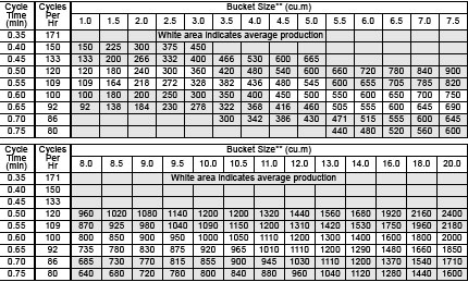
* Actual production = (Standard production) × (Bucket fill factor) × (Job efficiency)
** Bucket size: Heaped bucket capacity
Bucket fill factor (K)

Job efficiency (E)
